by Dr. Carol F. Milazzo, KP4MD (posted 03 September 2012)E-mail: kp4md@arrl.net The small magnetic loop antenna is a compact efficient antenna that is ideal for portable deployment or limited spaces and can be improvised inexpensively. The antenna is essentially a tuned circuit with an inductor formed by a loop of wire measuring less than 1/4 wavelength and resonated to the operating frequency with a capacitor. Since its radiation resistance is low and circulating current large, the loop must be constructed of a low resistance large outer diameter conductor for best efficiency. Typically these loops are built from coaxial cable, hardline, or copper or aluminum tubing. These loops have a very narrow bandwidth, requiring a variable capacitor (and preferably a reduction drive) for tuning to the operating frequency. As a voltage on the order of several thousand volts develop across the capacitor, air variables or vacuum variable capacitors are used. To maintain the lowest possible series circuit resistance, the connections are preferably soldered and a split-stator or "butterfly" capacitor is preferred. |
|
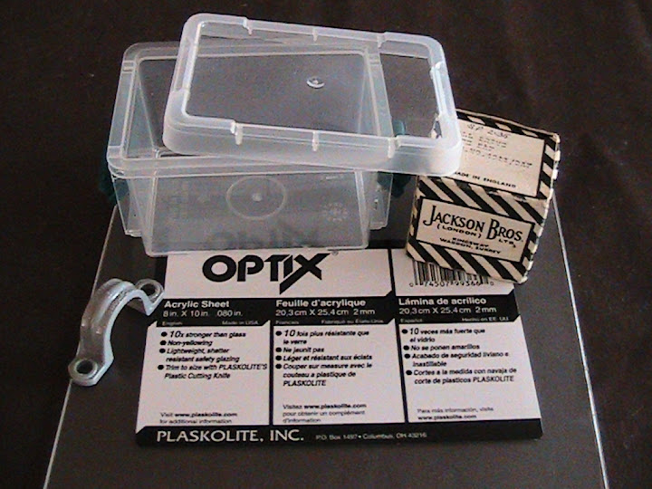
1. Materials used for the tuning enclosure: 3¼” x 2½” x 4½” craft storage box from Michael's (2 for $2.99), 1/2" conduit clamp (5/$0.99) and .08" acrylic sheet ($1.99) from Lowe's, and a Jackson Bros. 4511 DAF 6:1 planetary reduction ball drive.
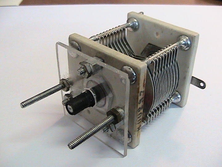
2. Butterfly capacitor ($5 at swap meet), 19 plates 1.5" diameter, 0.02" plate spacing provided a 12-58 pF tuning range. A piece of the acrylic sheet was cut and drilled with a Dremel tool and mounted to the front of the capacitor.
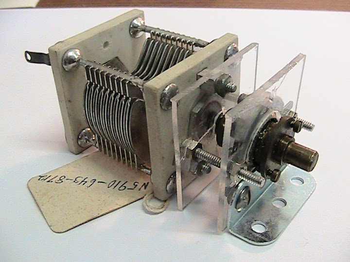
3. Another piece of acrylic sheet was cut and drilled to mount the reduction drive needed due to the very sharp tuning of the resonance point. Planetary ball drives are available through The Xtal Society and MFJ Enterprises. An angle bracket was attached to mount the assembly inside the tuning enclosure.
|

4. The assembled tuning enclosure. The shell of a SO-239 connector was soldered with 8 AWG stranded copper wire to each stator of the butterfly capacitor. The center pins and the capacitor rotor were left unconnected. The NE-2 neon lamp serves as a resonance indicator. Both leads of the lamp are soldered together to only one of the stator sections. The lamp is in the air about an inch away from the other stator section.

5. Schematic diagram of ferrite toroid core feed Magnetic Loop Antenna with variable transformer ratio. As described by G4FON on http://www.g4fon.net/MagLoopTwo.htm2, a 3 position switch was wired to vary the transformer ratio, selecting taps at either 5, 7 or 8 turns to achieve the lowest SWR on each frequency band.
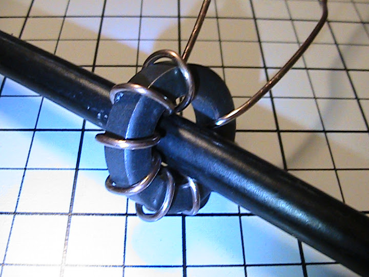
6. A wide-spaced 8-turn coil of 14 AWG solid copper wire was wound on an FT140-43 ferrite toroid core threaded over the loop wire (a 112 inch length of RG-8A/U coaxial cable terminated in PL-259 connectors). Taps would later be soldered on the 5th and 7th turns after mounting in the coupling enclosure. Spreading the coil turns over the full circumference of the core improves coupling, antenna Q and radiated field strength.
|

7. A view of the bottom of the coupling enclosure showing the 3 position switch and BNC connector. This switch was salvaged from a defunct blow dryer.
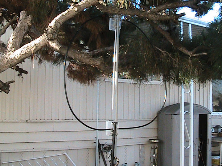
8. The magnetic loop antenna assembled on a 5 foot length of 1/2 inch PVC conduit and mounted on a tripod. The 112 inch loop of RG-8A/U cable is attached to the SO-239's on the tuning enclosure. The transmission line is RG-58/U coaxial cable coiled into 2 turns threaded through ferrite cores to form a choke balun at the feed point. The capacitor is adjusted using a vinyl mini-blind wand attached to the shaft of the reduction drive.

9. A close-up view of the tuning enclosure with the NE-2 neon lamp glowing at resonance. The tuning range of this capacitor allowed operation from slightly below 14 MHz to above 30 MHz. Attaching a 150 pF fixed capacitor in parallel across the butterfly capacitor allowed tuning over the 7 MHz band. A 47 pF capacitor in parallel allowed operation on the 10.1 MHz band.
|
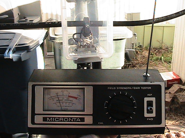
10. The capacitor is first adjusted for maximum received noise on the operating frequency, then fine tuned for lowest SWR while transmitting. Tuning for maximum brightness on the the neon lamp coincided with maximum deflection of the field strength meter and was sufficiently close to minimum SWR.

11. A view of the coupling enclosure on the assembled antenna. The 3 position slide switch selects 5, 7 or 8 turns of the primary winding on the ferrite toroid core. SWR was 1.1:1 or better at resonance. Best match occurred with the 5 turn tap on 25-28 MHz, the 7 turn tap on 21-25 MHz and the full 8 turns on 14-21 MHz. There was no perceptible heating of the core at 20 watts transmitted power. Higher power level was not used as it would exceed the capacitor voltage rating.
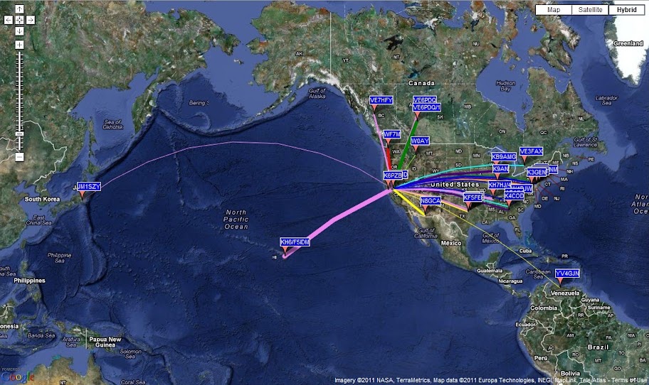
12. A test run of the magnetic loop antenna using 5 watt WSPR transmissions with a FLEX-1500 on 14 MHz yielded these confirmations of reception and transmission with Japan, Hawaii, Venezuela, Canada and the U.S. between 2226 UTC 01 JAN and 0356 UTC 02 JAN 2012.
|
REFERENCES- Magnetic Loop Antenna for 80-20 Meters, Doerenberg, F, N4SPP
- Portable Magnetic Loop Antenna Version Two, Goff, R, G4FON
- Small High Efficiency Loop Antennas, Hart, T, W5QJR
- Small Transmitting Loop Antennas, Yates, S, AA5TB
- A Universal HF Magnetic Loop NEC Model, Milazzo, C, KP4MD
- Magnetic Loop Antenna Project, River City Amateur Radio Communications Society
| LINKS
- Photo Album
- Magnetic Loop Antenna Club Project
- Magnetic Loop Antenna Yahoo Group